

1、Scope
1.1 This test method evaluates in a short period of time the low-voltage (up to 600 V) track resistance or comparative tracking index (CTI) of materials in the presence of aqueous contaminants.
1.2 The values stated in metric (SI) units are to be regarded as standard. The inch-pound equivalents of the metric units are approximate.
1.3 This standard is technically equivalent to the version of IEC Publication 112 cited in 2.2. However, the 2007 version of IEC 60112 Fourth Edition yields numerical CTI values that are very likely to differ significantly from this standard.
1.4 This standard does not purport to address all of the safety problems, if any, associated with its use. It is the responsibility of the user of this standard to establish appropriate safety and health practices and determine the applicability of regulatory limitations prior to use.
2、Terminology
2.1 Definitions:
2.1.1 track—a partially conducting path of localized deterioration on the surface of an insulating material.
2.1.2 tracking—the process that produces tracks as a result of the action of electric discharges on or close to an insulation surface.
2.1.3 tracking, contamination—tracking caused by scintillations that result from the increased surface conduction due to contamination.
2.1.4 tracking resistance—the quantitative expression of the voltage and the time required to develop a track under the specified conditions.
2.1.5 For other terminology, refer to Terminology D1711.
2.2 Definitions of Terms Specific to This Standard:
2.2.1 comparative tracking index—an index for electrical insulating materials which is arbitrarily defined as the numerical value of that voltage which will cause failure by tracking when the number of drops of contaminant required to cause failure is equal to 50.
2.2.1.1 Discussion—The voltage value is obtained from a plot of the number of drops required to cause failure by tracking versus the applied voltage.
2.2.2 failure, n—an attribute of an electrical circuit containing an electrical-current-sensing device that rapidly decreases the applied voltage to zero if the current in the circuit exceeds a predetermined limit.
3、Summary of Test Method
3.1 The surface of a specimen of electrical insulating material is subjected to a low-voltage alternating stress combined with a low current which results from an aqueous contaminant (electrolyte) which is dropped between two opposing electrodes every 30 s. The voltage applied across these electrodes is maintained until the current between them exceeds a predetermined value. This condition constitutes a failure. Additional specimens are tested at other voltages so that a relationship between applied voltage and number of drops to failure can be established through graphical means. The numerical value of the voltage which causes failure with the application of 50 drops of the electrolyte is arbitrarily called the comparative tracking index. This index provides an indication of the relative track resistance of the material.
4、Significance and Use
4.1 Electrical equipment can fail as a result of electrical tracking of insulating material that is exposed to various contaminating environments and surface conditions. There are a number of ASTM and other tests designed to quantify behavior of materials, especially at relatively high voltages. This method is an accelerated test which at relatively low test voltages, provides a comparison of the performance of insulating materials under wet and contaminated conditions. The comparative tracking index is not related directly to the suitable operating voltage in service.
4.2 When organic electrical insulating materials are subjected to conduction currents between electrodes on their surfaces, many minute tree-like carbonaceous paths or tracks are developed near the electrodes. These tracks are oriented randomly, but generally propagate between the electrodes under the influence of the applied potential difference. Eventually a series of tracks spans the electrode gap, and failure occurs by shorting of the electrodes.
4.3 The conditions specified herein are intended, as in other tracking test methods, to produce a condition conducive to the formation of surface discharges and possible subsequent tracking.
Test conditions are chosen to reproducibly and conveniently accelerate a process; for this reason, they rarely reproduce the varied conditions found in actual service. Therefore,while tracking tests serve to differentiate materials under given conditions, results of tracking tests cannot be used to infer either direct or comparative service behavior of an application design. Rather, tracking test results provide a tool for judging the suitability of materials for a given application. The suitability can only be verified through testing the design in actual end use or under conditions which simulate end use as closely as possible.
5. Procedure
5.1 Conduct the test in a draft-free, clean environment at a temperature of 20 6 5 °C.
5.2 Fill the dropping assembly with solution and set the counter to 0.
5.3 Set the power source to the desired voltage and adjust in accordance with 9.6.
5.4 Place the test specimen on the supporting platform so that the electrodes can be placed on the specimen.
5.5 Position the electrodes as shown in Fig. 2 so that the chisel edges contact the specimen at a 60° angle between electrodes and so that the chisel faces are parallel in the vertical plane and are separated by 4 6 0.2 mm (0.16 in.).
NOTE 1—It is recommended that contact of the electrodes with the specimen shall be such that when a light source is so placed that the light reaches the eye along the surface of the specimen, no light is visible between the specimen and the electrodes. If light is visible due to the electrode edges having become rounded, the edges must be reground.
5.6 Open the shorting switch and begin the sequence of drops with the time interval between drops set at 30 6 5 s.
5.7 Continue until tracking occurs. This condition is usually well defined with a sudden surge occurring in the current(from essentially 0 to almost 1 A) accompanied by a corresponding drop in voltage.
5.8 A test is permitted to be repeated on a given specimen provided the electrode gap is positioned a minimum of 25 mm (1.0 in.) from any specimen area affected by a previous test or from any edge. The position of the new test must be clean and un-splashed with electrolyte from a prior test.
5.9 Obtain one reading on each of five specimens of a sample to be tested at any given voltage. Repeat this process in accordance with 10.8, at different voltage levels such that at least two levels produce failures in less than 50 drops and two levels greater than 50 drops.
5.10 Limit any test voltage to 600 V or less. Testing at higher voltages will generate electric discharges above the surface of the specimen, which will produce erroneous results.
5.11 When testing at voltages below 150 V, and there is not sufficient energy to vaporize completely the electrolyte solution that has been placed between the electrodes, flooding can result. If flooding occurs, discontinue the test.
6. Calculation
6.1 Plot the number of drops of electrolyte at failure versus voltage. On the curve note the voltage which corresponds to 50 drops. This is the comparative track index (CTI) (see Fig. 3).
7. Report
7.1 Report the comparative tracking index for each material tested, and include the following:
7.1.1 Description of the material tested,
7.1.3 Test temperature,
7.1.4 Test voltage and number of drops of electrolyte to failure, for each test,
7.1.5 The CTI value in volts derived in accordance with 11.1, and
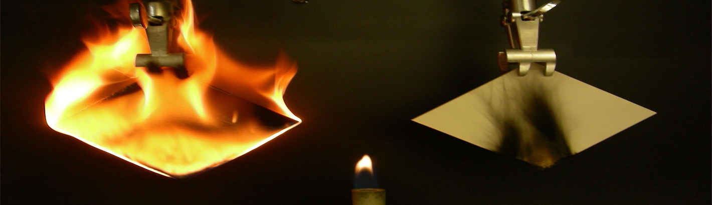
7.1.6 Visual observations of specimen behavior, such as elting of the specimen, flame ignition (if it occurs), and the ype of erosion that has occurred on the surface of the test pecimen between the electrodes.
7.1.2 Resistivity of the electrolyte